
VCC® Compressor – Technician Training & Diagnostic Guide
Internal training reference for Advance Appliance Ltd technicians. This guide explains how VCC (Variable Capacity) compressors work, how speed is controlled, and how to safely diagnose compressor, inverter, and control faults.
For additional field safety requirements, see our safety tools and procedures guide .
Core Concept
How the VCC Compressor Works
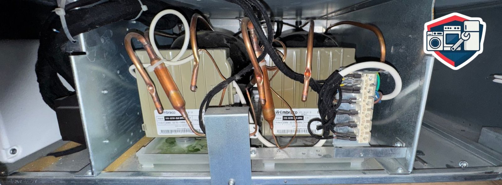
A VCC (Variable Capacity Compressor) is controlled by a frequency (inverter) control board mounted next to and wired to the compressor. The VCC runs at various speeds depending on the thermal load in the refrigerator and the ambient temperature.
- Stabilizes cabinet temperature faster than a conventional ON/OFF compressor.
- Uses less electricity than a conventional compressor of the same size.
- Does not go through a high-amperage hard start like a relay-driven unit.
- Compressor speed is controlled via the ambient air NTC (thermistor).
The starting speed and subsequent speed increases depend on the ambient temperature registered by the NTC and the total compressor runtime.
Compressor RPM by Ambient Temperature (Normal Operation)
Ambient ≤ 95°F (≤ 35°C)
2000 rpm
95–98.6°F (35–37°C)
3000 rpm
Ambient > 98.6°F (> 37°C)
3500 rpm
Super / Boost Mode
4000 rpm
First speed increase: after ~80 minutes of continuous operation (or ~60 minutes after defrost) the compressor increases by ~600 rpm. Second increase: after a further ~30 minutes, another ~800 rpm. Speed is not reduced while the compressor is running.
Frequency & Speed Control (Inverter Output)
The power electronic (inverter) uses discrete output frequencies to control compressor speed. Each frequency corresponds to a specific rpm and cooling capacity.
| Frequency (Hz) | Speed (rpm) | Typical Use |
|---|---|---|
| 53.3 Hz | 1600 rpm | Low cooling demand / energy-saving mode |
| 73.3 Hz | 3600 rpm | High cooling demand / Super mode |
| 100.0 Hz | 3000 rpm | Normal operation at warmer ambient |
| 116.7 Hz | 3500 rpm | High ambient / heavy load |
Higher frequency = higher rpm = more cooling. The system may also default to ~3000 rpm if the ambient air NTC is defective (failsafe behavior).
Note: Long run time at low to medium rpm is normal for VCC systems. They are designed to run
longer at lower power to save energy and keep temperature more stable.
⚠
Critical Warning: The VCC compressor can only be operated via the electronic inverter.
Direct activation with supply voltage (line voltage) will destroy the compressor winding.
Never apply 120VAC/240VAC directly to compressor terminals.
⚠
Three-Phase Output – Do Not Voltage Check: VCC compressors are three-phase inverter-driven motors.
The U–V–W terminals carry a high-frequency PWM signal, not a standard AC waveform. Do not
perform voltage measurements on these terminals with a normal voltmeter. Test frequency output and
winding resistance only. Always follow
internal safety procedures
.
Resistance & Temperature: The measured resistance value may deviate slightly due to temperature
fluctuations in the compressor windings. ~16 Ω ±0.5 Ω at 75°F (24°C) is the reference.
Slightly lower readings when cold and slightly higher readings when warm are normal as long as all three readings are equal.
Compressor Coil Testing (VCC Motor Health)
These tests are done with power off. They confirm if the three-phase compressor motor windings are electrically healthy before further control or inverter diagnosis.
Three Coils on Compressor – Resistance & Ground Check
1. Coil-to-Coil Resistance
- Label the compressor terminals U, V, and W (three-phase).
- Measure resistance between U–V, V–W, and U–W.
- All readings should be approximately the same.
- Reference value: ~16 Ω ±0.5 Ω at 75°F (24°C).
Small variations due to temperature are acceptable as long as all three readings are equal. If one reading is significantly higher or lower than the others, the winding is likely defective.
2. Coil-to-Ground Test
- Measure from U → Ground, V → Ground, W → Ground.
- There should be no continuity to ground (meter reads OL / Infinite).
| Test Result | Interpretation | Action |
|---|---|---|
| All three readings ≈16 Ω, equal | Healthy windings | Proceed to wiring & control tests |
| One reading much lower | Shorted turn / short-circuited coil | Replace compressor (sealed-system repair) |
| One reading much higher | Open winding / interruption | Replace compressor (sealed-system repair) |
| Any coil to ground continuity | Grounded compressor | Replace compressor (sealed-system repair) |
If the measured resistance values deviate significantly (short circuit, interruption, or short-circuited coil), the winding is defective and the compressor must be replaced via a sealed-system repair.
Wiring, VCC Controls & Non-Start Diagnosis
If the compressor windings test correctly, the next steps are to verify wiring from the control to the compressor, test alternate control modules, and determine if the compressor is seized.
1. Wiring From VCC2 Control to Compressor
If correct resistance values are measured on the compressor, check for continuity in the leads from the VCC2 control module to the compressor.
- Check all three motor leads (U, V, W).
- Inspect harnesses and connectors for breaks, corrosion, or heat damage.
- If any leads or connectors are broken, repair or replace them.
2. VCC2 to VCC3 Control Swap Test
If all leads and connectors are in order and the compressor still does not run, remove the VCC2 control and replace it temporarily with a VCC3 control.
- VCC3 controls do not have a speed-control connection.
- Power the appliance with the VCC3 installed.
- The compressor should start after approximately 90 seconds.
| VCC3 Test Result | Interpretation | Next Step |
|---|---|---|
| Compressor starts after ~90 s | Compressor & wiring OK, VCC2/control signal suspect | Proceed to VCC Control Testing (speed-signal voltage) |
| Compressor does not start | Possible seized compressor or inverter fault | Evaluate inverter output; likely sealed-system compressor replacement |
3. Compressor Non-Start & Seized Condition
If the compressor does not start after approximately 2 minutes of receiving a valid start command and correct inverter output, the compressor is considered seized.
- Internal mechanical components are locked and cannot rotate.
- Even if windings test good, the rotor/pump assembly may be mechanically stuck.
- A sealed-system repair will be required to replace the compressor.
VCC Control Voltage & Speed-Signal Testing
These tests confirm that the VCC control is powered correctly and that the power electronic is sending the correct DC speed-control signal.
1. Line Voltage to VCC Control – Supply Check
Step A – Check at Terminal Block
- With the appliance connected to power and switched ON, measure voltage at the main terminal block.
- There should be approximately 120VAC going to the appliance/VCC control.
- If there is no voltage, check the wall outlet, breaker, and any GFCI/AFCI devices.
Step B – Check at VCC Control Input
- Test for voltage (~120VAC) directly at the VCC control power input.
- If 120VAC is at the terminal block but not at the VCC control, there is a wiring/harness issue.
- If 120VAC is at the VCC control input and it does not power up/respond, the VCC control is likely defective.
| Test Location | Reading | Diagnosis |
|---|---|---|
| Terminal block | ~120VAC | Household supply OK |
| Terminal block | 0VAC | Outlet / breaker / supply issue |
| VCC control input | 0VAC but 120VAC at block | Wiring / harness fault to VCC control |
| VCC control input | 120VAC but no operation | Faulty VCC control module |
⚠
High Voltage: 120VAC can be lethal. Use proper PPE, insulated probes, and lock-out/tag-out procedures where applicable.
Never touch compressor or inverter terminals while energized.
2. VCC Control Speed-Signal Voltage Check
With the VCC3 control still in the appliance, check the voltage at the speed-control connector while the appliance is turned ON.
- Use a DC voltmeter.
- Measure the DC signal voltage at the speed-control connection.
| Measured DC Voltage | Interpretation | Action |
|---|---|---|
| Between 1 and 10 VDC | Power electronic is sending a valid speed-control signal. | Install a new VCC2 control (with speed-control connection). |
| 0 VDC | No speed-control signal being sent. | Replace the power electronic and reinstall the original VCC2 control. |
| Above 10 VDC | Invalid / out-of-range signal from power electronic. | Replace the power electronic and reinstall the original VCC2 control. |
Summary: If the speed-signal voltage is 1–10 VDC, the inverter is good and the VCC2 control is suspect. If the speed-signal voltage is 0 VDC or >10 VDC, the inverter (power electronic) is faulty and must be replaced.
Quick Diagnostic Flow – VCC Compressor Will Not Run
1. Supply Power
Confirm ~120VAC at terminal block and at VCC control input. Repair outlet, breaker, or wiring if missing.
2. Coil Tests
Power off. Measure U–V, V–W, U–W and to ground. If values off or grounded, replace compressor (sealed system).
3. Wiring Check
Verify continuity from VCC2 control to compressor terminals. Repair/replace any damaged harness or connector.
4. VCC3 Swap
Install VCC3 control. If compressor starts in ~90 s, compressor & inverter OK; proceed to speed-signal voltage test.
5. Speed Signal
Measure 1–10 VDC at speed-control connector. 1–10 VDC → replace VCC2; 0 or >10 VDC → replace power electronic.
6. Seized Check
If all signals are correct and compressor still does not start within ~2 minutes, diagnose a seized compressor and perform sealed-system replacement.
Customer-Friendly Explanation (Optional Use):
The fridge uses a variable-speed compressor, similar to a dimmer switch for a light. Instead of constantly turning on and off at full power,
it gently speeds up or slows down to keep temperature stable while using less electricity. Longer, quieter run time is normal for this type of system.
For more common-language explanations you can share with customers, see our
appliance common issues guide
.
Inverter (Variable-Speed) Appliance Systems – Quick Guide
Training reference for Advance Appliance Ltd. Explains which brands commonly use inverter technology and the key pros and cons for both customers and technicians. For deeper sealed-system diagnostics, see our internal VCC / inverter compressor guide .
Common inverter brands
Appliance Brands That Commonly Use Inverter Technology
Many newer mid- to high-end appliances now use inverter or variable-speed compressors/motors:
- LG – “Inverter Linear Compressor”, “Direct Drive Inverter Motor”.
- Samsung – “Digital Inverter Compressor” and “Digital Inverter Motor”.
- Whirlpool / Maytag / KitchenAid / Amana – Inverter compressors and variable-speed drives on high-efficiency models.
- Bosch / Siemens – Inverter compressors and EcoSilence™ motors.
- GE / Haier / Café / Monogram – Premium and luxury models with inverter compressors.
- Midea / Hisense / Danby and other OEMs – Inverter systems on newer energy-saving fridges and AC units.
- Mitsubishi / Daikin / Panasonic / Fujitsu (HVAC & mini-splits) – Almost all units are inverter-driven.
In customer language: most newer mid- to high-end fridges, washers, dryers, and ductless systems now use inverter/variable-speed motors instead of basic ON/OFF designs.
What inverter means
What Is an Inverter / Variable-Speed System?
An inverter system uses electronics to control the speed of the compressor or motor instead of simply turning it fully ON or fully OFF.
- Runs at different speeds depending on load and temperature.
- Uses a control board and inverter module to create a 3-phase output.
- Behaves like a “dimmer switch” for cooling or motor speed instead of a simple on/off switch.
This is the same concept as VCC (Variable Capacity Compressor) in your sealed system and VCC training modules.
Pros of Inverter Systems
Key benefits you can highlight to customers, plus performance advantages your technicians should know.
Customer benefits
For Homeowners
- Quieter operation – no loud hard-start; ramps up and down smoothly.
- Better temperature control – more stable fridge/freezer temps and better food preservation.
- Lower energy use – adjusts capacity to actual demand instead of always running full power.
- Less stress on components – fewer high-amperage starts can reduce mechanical wear.
Technical advantages
For Technicians & System Performance
- More precise control – controller can tune speed based on ambient, usage, and defrost cycles.
- Better performance in tough conditions – can speed up at high ambient or in boost/super modes.
- Diagnostic visibility – fault codes, LEDs, frequencies, and speed data help guide troubleshooting.
- Optimized run profile – longer low-speed runs improve stability and efficiency.
Cons and Trade-Offs of Inverter Systems
Explains why inverter repairs can be more complex and costly, and where Advance Appliance Ltd can stand out.
Customer trade-offs
For Homeowners
- Higher repair costs – failures usually involve control boards, inverters, or sealed systems, not cheap relays.
- Power-sensitive – surges, brownouts, and dirty power can damage inverter electronics.
- Not DIY-friendly – high-voltage electronics plus sealed-system work require a qualified technician.
Service complexity
For Technicians & Operations
- Higher skill requirement – need to understand 3-phase inverter motors, DC bus, PWM, and speed signals.
- Parts availability – OEM boards and inverters may be expensive or on backorder.
- More diagnostic steps – must verify power, control board, inverter, sensors, and compressor mechanics.
This justifies premium diagnostic and sealed-system rates for inverter/VCC jobs.